Design Features
Below is a brief overview of each of our project's subsystems and the major design decisions that factored into our final product.


01
Structure
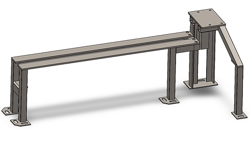
The Structure subsystem comprises of the bed, ways, sheet metal enclosure, and support beams for the transmission and motor mounting. The main bed has steel ways that allow the tool rest and tailstock to move closer to or further away from the headstock. It is bolted to the rest of the structure to allow for realignment. The headstock and transmission are supported by a plate at the wider end of the structure, which also supports the motor. We have designed our structure with the motor mounted to a plate, which rotates to tension and de-tension the belt in order to switch the transmission between different speeds.
02
Headstock
The headstock is composed of three main parts: the spindle, the spindle housing, and the mounting block. The headstock interfaces between the step pulley and belt on the drive side, and the chuck and workpiece on the spindle nose side. The headstock enables a freely rotating workpiece and reacts against the cutting loads. To begin the design process for the headstock, a list of detailed requirements were set out to narrow the design space. Read more about it on our Spindle Deep-Dive page!


03
Transmission
The transmission is primarily composed of one v-belt and a set of step pulleys which run between the motor shaft and the back end of the spindle. This is a 3-in-one pulley which has 3 distinct diameters along it. By running a belt between two of these we can achieve a variety of belt ratios within a very compact area. One must simply pull the belt off of one set of pulleys and shift it onto the next in order to change speeds. To perform this belt change we implemented a belt de-tensioning system. The entire motor is mounted to a pivot plate. If you loosen this plate the motor can pivot up and down relieving tension from the belt and allowing you to switch its position on the pulleys.
Our motor is a .5hp 120V Single Phase AC motor with two speed options (1125, and 1740) which we salvaged from a worn-out washing machine. These two options along with 3 belt ratios provides the lathe with up to 6 usable speeds from 500 – 3500 RPM.
04
Tool Rest
The Tool Rest subsystem is a multi-axis adjustable support and guide which sits on the bed for wood lathe tools to be held against for stability when turning. Our design locks its position on the bed into place using a CAM locking mechanism. The hand/tool rest piece was designed with ergonomics, function, and ease of machining in mind. It is the perfect length for turning pens with the mandrels in Olin’s shops and was machined out of steel for extra strength. The retention of the rest piece was also designed to allow for rotation and height adjustment.

05


Tailstock
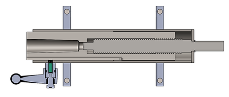
The Tailstock subsystem is designed to increase the utility of our wood lathe. It allows for supporting longer workpieces from the other side using a center, critical to many turning techniques. Additionally, it has 3.5” of travel using its handwheel, allowing for drilling operations. Inside the cylinder consists of a screw mechanism which actuates the tailstock spindle axially when the handwheel is turned. The other end of this has the same mating taper as the headstock for holding tools. When the tailstock is pulled back to the end of its travel any wool within this taper is bumped out for easy removal.
Furthermore, you can lock the spindle of the tailstock in place for holding stock, and you can knock out your tools by pulling the spindle back into the housing. The spindle utilizes a mating feature with the bed to hold it parallel with the bed and in line with the main spindle as well as an eccentric CAM locking mechanism to hold it in place. The tailstock housing is mounted onto its base by clamping side panels.
06
Electrical
Our electrical system is designed to be safe and simple. Power comes into the lathe through a Nema iec320 connector. The lathe itself is run off 120v wall power. From there the hot line goes through a fuse for safety in the case of shorts. The hot and neutral go through an on-off power switch that stays pressed in its current state. The neutral connects to the main and starter coils on the motor, while hot goes through on-on switch to select speed. The 1 setting sends power to the low-speed coils and 2 sends it to the high-speed coils. Either setting will also send hot to the starter coil. When the switch is set to zero the starter coil does not have power to prevent it from overheating. The ground wire from the wall goes to a bolt on the chassis as well as the motor.

