Design Evaluations
Cutting Loads / Required Power
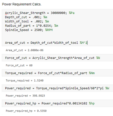
We calculated an estimate of what cutting loads our spindle would experience to ensure its design would hold up to repeated loading. To do this, we estimated the area of the of contact a cutter to be 2mm^2. We then estimated the shear strength of a very hard wood or acrylic to be 30MPa and found the required force needed to exceed that stress in the cutting area. This gave us a cutting load of approximately 60N. (This is a fairly high estimate as the estimated depth of cut and shear strength were much than reality.)
To get an estimation of the required power our motor would need to provide to take this cut we simply multiplied the estimated force by our expected part radius. This gave us an estimated torque required of 1.52 Nm. We then multiplied this torque by the spindle speed to estimate a required power of ~400W or .5hp. Using this estimate we were able to specify our motor to .5hp.

General Torque & Speed Calculations
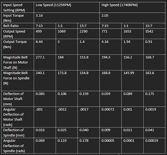
We first wished to determine the torque of our motor given the rated power. We used the equation seen below accounting for the efficiency of the motor. Our motor has two speed settings, so this gave us an estimated output torque of 3.1Nm at a speed of 1125RPM and an output torque of 2Nm at 1740 RPM.
We then calculated simple ratios to determine our output speeds and torques for each motor speed and belt setting, these can be seen in the table below. We use 3 staged step pulleys in our system with pitch diameters of 1.75in 2.75in, and 3.75in. In our chosen configuration, this gives us transmission ratios 7:15, 1:1, and 15:7. We also included an assumed efficiency of .95% through our belt.

Belt Force Calculations
With the known forces created from our belt, we were able to calculate expected deflections on both the motor and spindle shaft for each speed configuration. To do this, we approximated each shaft as a bending beam with the scenario pictured below. The shaft is supported on one end with a force along its length.
With this scenario we are able to use pre-determined beam bending equations to calculate the deflection of out motor shaft and spindle. We simply used the normalized force of the belt as a total force acting on the shaft (shown in the table), the moment of inertia for the shafts given as
for a circle and
for a hollow shaft, and the location along the shaft determined by which pulley is being used along the steps.
We found the deflection to remain under .15mm, within the safe operating range of v-belt pulleys. Specific values for deflections can be found in the table below.
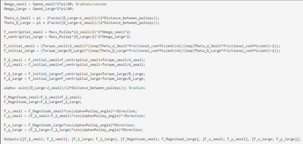
We conducted belt calculations to determine the forces in the x and y directions on our shafts. Our belts forces are determined by a function that is reliant on a series of inputs: Torques and speeds of the two sides, diameters, frictional coefficient, distance between the pulleys, and the mass of the pulleys. The first step from there was to calculate the angle of contact with the two pulleys based on the two pulley diameters and the distance between the pulleys. The centripetal force is then calculated from mass, diameters, and speeds. Additionally, the initial force is calculated based on the torques, diameters, and frictional coefficients on the parts. Using the initial force and centripetal force the tensional forces tangential to both sides of the pulley can be calculated, F1 and F2 for each pulley. Finally, based on the angle of the tensions angle relative to the x and y reference frame (alpha), we can get x and y components of the overall belt forces.
We found resultant loads in the range of 50 to 300 newtons which match what we expected. We used these values to calculate deflection of our shafts.
Our given pulleys are able to take a type 4L and size A v-belt. Given our calculated loads, the lower strength 4L v-belt likely would have been sufficient. However, we purchased a type A belt meant for higher torque uses as the price was similar.
Motor & Spindle Deflection Due to Belt


Drilling Load Calculations
We did drilling load calculations to ensure that our tailstock would be able to handle the loads it would see. We started by setting some constants: a flute angle of 35 degrees, flute engagement of 1 mm, and a ½ in drill bit, and an acrylic workpiece (this is about as high load of a case as we would see). From those constants we calculated drilling contact area and the shear force that would be caused by acrylic’s shear strength across that area. We then pulled out the axial component of that force and compared it to the cross section of the area supporting the load. This gave us a stress of less than 3x10^6, far lower than the yield strength of the steel cap that will be resisting these loads.

Structure FEA
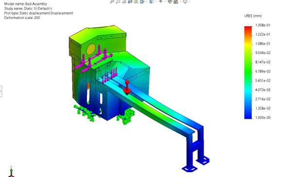
To ensure our structure would properly support the loads it would see we conducted a structural static FEA on the bed, chassis, and sheet metal. The feet of the lathe were fixed and components were treated as bonded (which is fair considering the components are either welded or connected with over specced bolts). Gravity was applied to the body and a load of 200N was applied on the bed representing the loads that would go down to the from the toolrest and onto the bolt holes where the spindle attaches to the assembly. Maximum deformation was .138mm and maximum stress was 7.794E7 far under the yield strength of 1.8E8. This study confirmed that our bed and structure would be more than strong enough for the expected use case.


Fatigue Analysis
A fatigue analysis was conducted in Solidworks simulation based on our structural FEA results. This informed us that our loads were well below the endurance limit and not significant enough for any gradual fatigue to cause failure over a reasonable time scale.
